
NPN Transistor Tutorial - The Bipolar NPN Transistor WebThis operating point is also called as quiescent point or simply Q-point.
#ACTIVE REGION OF TRANSISTOR DEFINITION PDF#
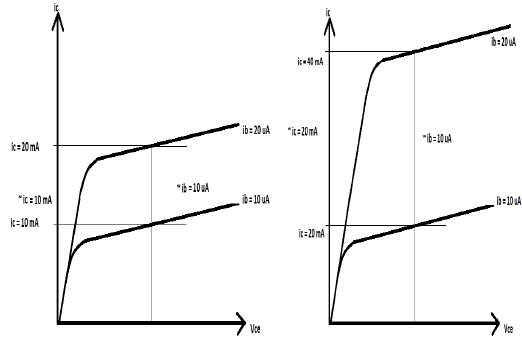
WebUntitled - Free download as PDF File (.pdf), Text File (.txt) or read online for free.Ĭharacteristics of a Transistor - Input, Output and Current …īipolar Junction Transistor - Engineering LibreTexts If you extend the horizontal axis to the right, you obtain curves like these. The flat regions are in fact where the transistor is operating in its linear region.How can I prove that the NPN BJT is in the active region? Graph of operating regions of npn transistor mean The npn device has one p region between two n regions and the pnp device has one n region between two p …

The BJT is fabricated with three separately doped regions. The BJT symbols and their corresponding block diagrams are shown on Figure 1. WebThe BJT is a three terminal device and it comes in two different types. Transistor Cut off, Saturation & Active Regions - Inst Tools How is the … trevor southersĭifferent Regions of BJT Operation - Electronics… CircuitBread graph of operating regions of npn transistor mean Of course, it is possible with a 0.7 Volt battery, but I think that is not how computers operate. The base must be charged with greater than 0.7 Volts in order for there to be an electric current in the main circuit. Where $I_$ = base current.Graph of operating regions of npn transistor npn - Transistor collector emitter saturation voltage - Electrical. As it is understood that, in the saturation region the transistor tends to behave as a closed switch, we can say that, The transistor operates in saturation region when both the emitter and collector junctions are forward biased.

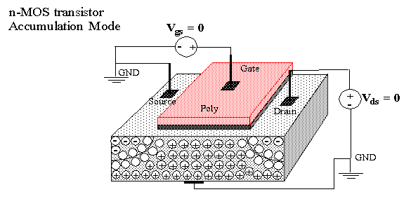
The figure below shows a transistor working in saturation region. The collector and Emitter currents are maximum in this mode of operation. The transistor has the effect of its collector and Emitter being shorted. This is the region in which transistor tends to behave as a closed switch. In the active state, collector current is β times the base current, i.e., The transistor operates in active region when the emitter junction is forward biased and collector junction is reverse biased. This region lies between saturation and cutoff. A transistor while in this region, acts better as an Amplifier. This is the region in which transistors have many applications. EMITTER JUNCTIONĪmong these regions, Inverse active region, which is just the inverse of active region, is not suitable for any applications and hence not used. This is understood by having a look at the following table. These biasing methods make the transistor circuit to work in four kinds of regions such as Active region, Saturation region, Cutoff region and Inverse active region (seldom used). Either forward or reverse biasing is done to the emitter and collector junctions of the transistor. The supply of suitable external dc voltage is called as biasing. Reverse biased is the condition where a positive voltage is applied to the n-type and negative voltage is applied to the p-type material. Forward biased is the condition where a positive voltage is applied to the p-type and negative voltage is applied to the n-type material. The junctions are forward biased and reverse biased based on our requirement. This DC supply is given to the two PN junctions of a transistor which influences the actions of majority carriers in these emitter and collector junctions. The DC supply is provided for the operation of a transistor.


 0 kommentar(er)
